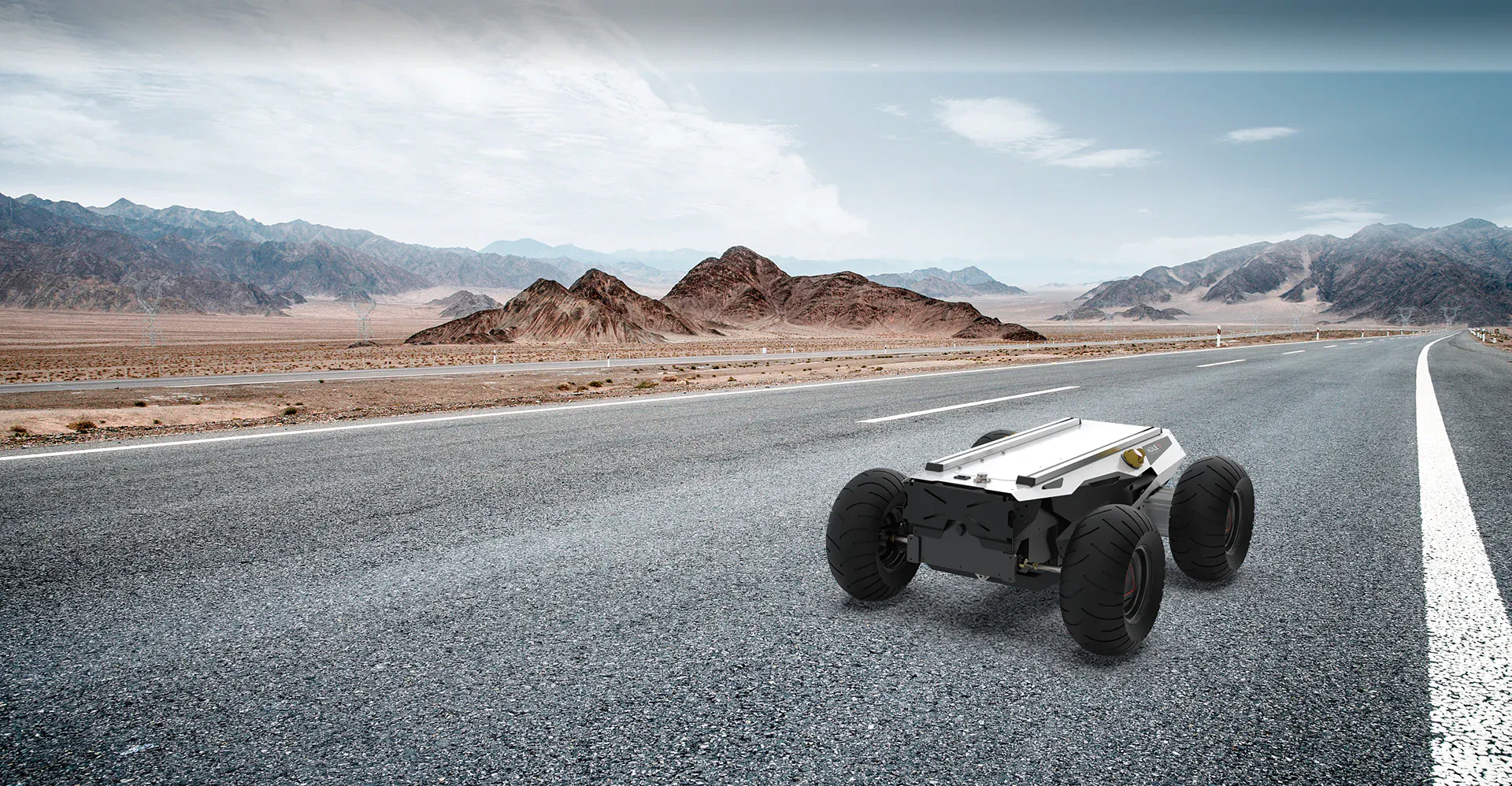
The HUNTER 2.0 is a programmable unmanned ground vehicle (UGV) platform built on an Ackermann
steering chassis. It offers car-like handling while providing superior performance on
Portland cement and asphalt surfaces.
Compared to traditional four-wheel differential drive chassis, HUNTER 2.0 delivers:
Enhanced payload capacity
Higher top speed
Reduced wear on tires and structure for long-term use
While not intended for extreme off-road terrain, the chassis features a rocker arm suspension
that allows it to overcome common obstacles such as speed bumps.
Optional modules such as stereo cameras, LiDAR, GPS, IMU, and robotic arms can be integrated
for advanced navigation, perception, and automation tasks.
HUNTER 2.0 is ideal for:
Autonomous driving research and education
Indoor and outdoor security patrols
Environmental monitoring and sensing
General logistics and material transportation
Component List
Name
Quantity
HUNTER 2.0 Robot body
x1
Battery charger (AC 220V)
x1
Aviation plug (male, 4-pin)
x1
Remote control transmitter (optional)
x1
USB to CAN communication module
x1
Specifications
Mechanical
Parameter
Value
Dimensions (L × W × H mm)
980 × 745 × 370
Wheelbase (mm)
650
Front / rear wheelbase (mm)
605
Weight of chassis body (kg)
65 / 70
Maximum steering angle
33°
Suspension type
Front wheel non-independent
IP rating
IP22
Electrical System
Parameter
Value
Battery type
Lithium battery
Battery capacity
24V 30Ah / 60Ah
Charging time
3 h (30Ah) / 6 h (60Ah)
Maximum battery life
Up to 8 hours
Working temperature
-10 °C to 40 °C
Drive System
Parameter
Value
Drive motor type
DC brushless
Drive motor power
2 × 400 W
Drive motor reduction ratio
1 : 40
Drive motor sensor
Magnetic encoder(2500 P/R)
Steering motor type
DC brushless 400 W
Steering type
Front-wheel Ackermann
Parking brake
Power-off electromagnetic
band-type brake
Control System
Parameter
Value
Control mode
Remote control / Command mode
RC transmitter
2.4 GHz, up to 200 m range
System interface
CAN
Performance
Parameter
Value
Maximum speed
1.5 m/s
Minimum turning radius
330 mm (approx.)
Maximum gradeability
10°
Ground clearance
100 mm
Maximum travel distance
40 km (24V 60Ah battery)
20 km (24V 30Ah battery)
Note
Performance values are based on standard test conditions.
Actual performance may vary depending on payload, terrain, and battery condition.
Safety Notes
Note
Intended for research, educational, and civilian applications only.
Do not modify electrical or mechanical systems without technical approval.
Always follow safety guidelines when operating the robot.
Environment
Note
IP22 protection rating safeguards against limited dust and vertical water droplets.
Not suitable for heavy rain or submerged operation.
Development
HUNTER 2.0 supports optional FS RC transmitter control, allowing manual operation of
movement and steering.
The CAN interface enables custom development and expansion of the platform.
Note
Remote control requires the optional FS RC transmitter.
CAN ports are designed for advanced user development and integration.
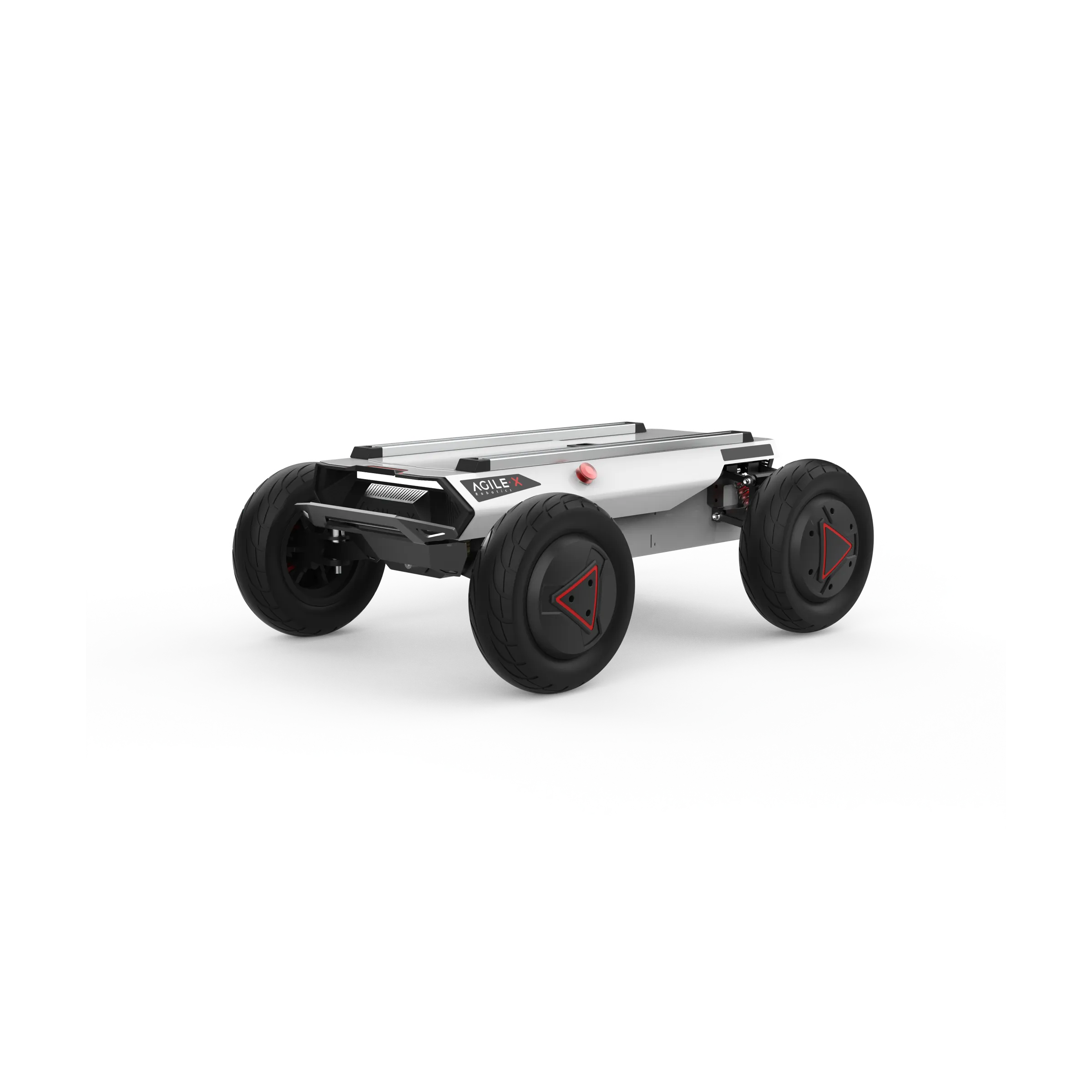
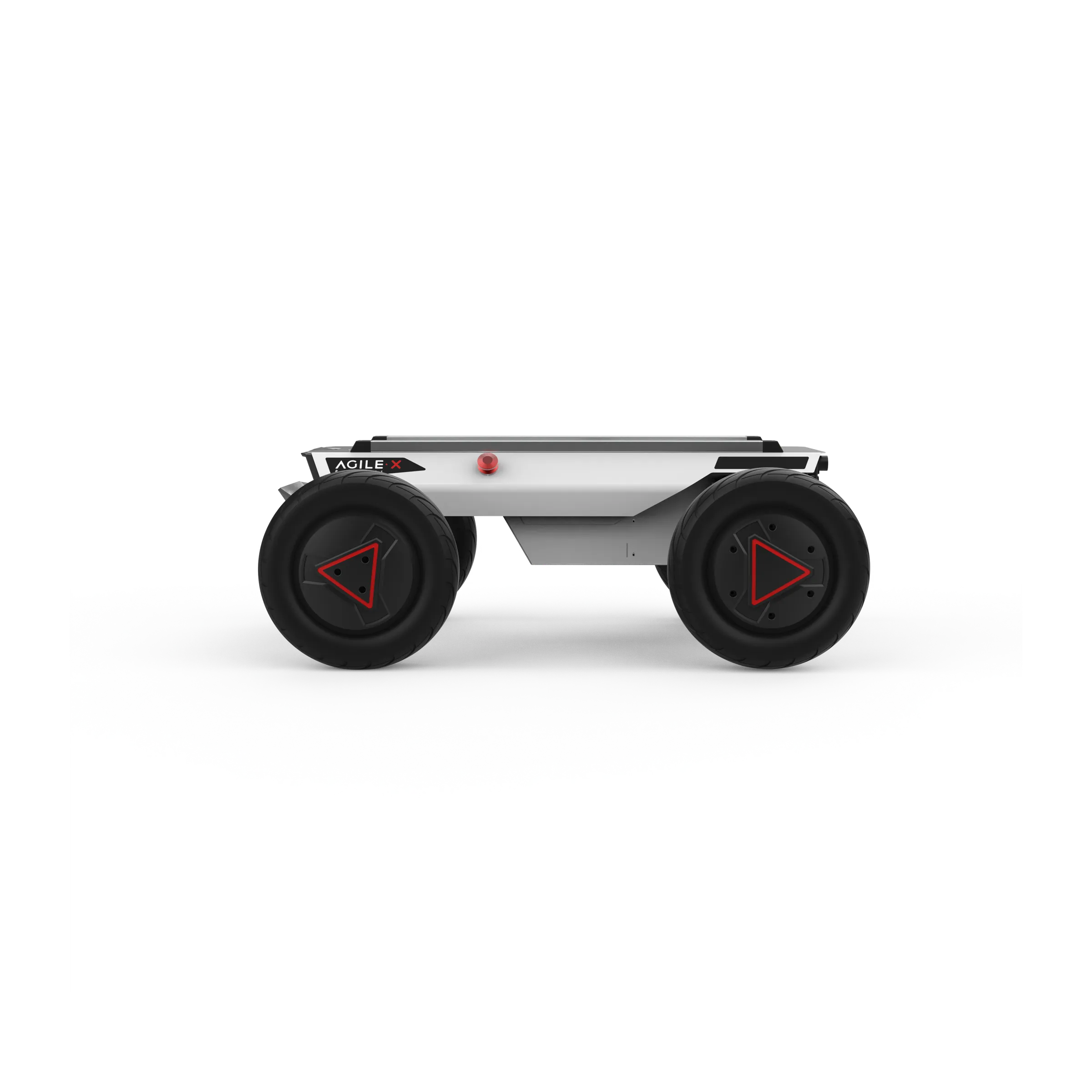
The Basics
This section introduces the HUNTER 2.0 mobile robot platform (see Figure 2.1 and 2.2).
Front View Components:
Standard Aluminum T-Slot Profile – Provides modular mounting support for sensors and accessories.
Top Cabin Panel – Main protective cover for electronic and mechanical components.
Top Extension Interface – Connectors for CAN, power, and optional device integration.
Emergency Stop Switch – Immediately cuts power to the robot in case of emergency.
Ackermann Front-Wheel Steering – Provides precise steering similar to automotive Ackermann geometry.
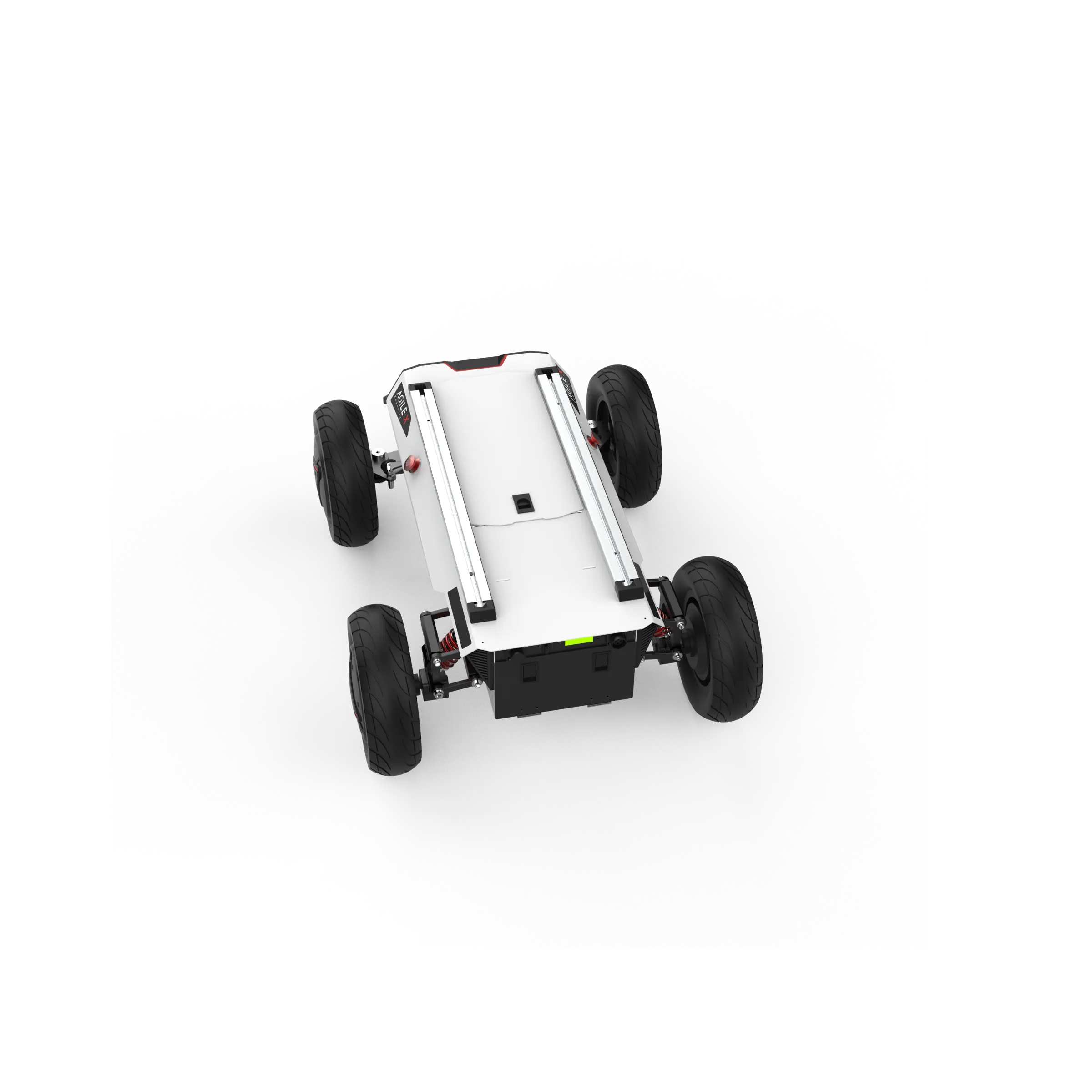
Rear View Components:
Emergency Stop Switch – Safety switch for immediate power cutoff.
Battery Replacement Panel – Access panel for battery installation or replacement.
Rear Panel – Houses power switches, CAN and 24V extension interfaces, and status indicators.
HUNTER 2.0 is designed as a versatile autonomous chassis that combines inflatable rubber wheels
with an independent suspension system. Coupled with powerful DC brushless servo motors, the
robot can traverse a variety of ground surfaces with high adaptability and obstacle passability.
An emergency stop switch is installed at the rear of the chassis to immediately cut power in case
of abnormal behavior or emergency situations.
The robot is equipped with waterproof connectors for both DC power and communication interfaces
on the top and rear panels. These connectors allow safe integration of external devices while
protecting internal electronics even in harsh or humid environments.
Note
Keep the emergency stop switch easily accessible at all times.
Only use waterproof connectors in environments with potential water exposure or high humidity.
Status Indication
The operational state of HUNTER 2.0 can be monitored via:
Voltmeter – shows battery voltage
Beeper – alerts for warnings or abnormal conditions
Indicator lights – display chassis status
These components are mounted on the chassis body. A summary of the indicators is provided below:
Status Indicators
Status
Voltage / Condition
Description
Battery voltage
Normal operating voltage
The current battery voltage can be read from the voltmeter
on the rear electrical panel.
Low battery alarm
< 24.5 V
(SOC < 15% with BMS)
The chassis emits a repeated “beep-beep-beep” warning when
battery voltage is low.
Replace battery
< 24.0 V
(SOC < 10% with BMS)
The system cuts off power to external extensions and drive
motors to prevent battery damage. Movement control and
external commands are disabled.
Robot powered on
Power ON state
Rear indicator lights are switched on.
Note
All voltage thresholds assume connection to the Battery Management System (BMS).
Regularly monitor the voltmeter and beeper to ensure safe operation.
Electrical Interface
Top Interface
The HUNTER 2.0 platform is fitted with two 4-pin aviation connectors and one DB9 (RS-232) interface on the top panel. In the current hardware version, the RS-232 port is used only for firmware updates and does not support command communication.
The physical locations of the aviation connectors and the DB9 interface are illustrated in Figure 2.3.
Expansion ports are available on both the top surface and the rear of the robot. Each expansion port includes:
A dedicated power supply output
A CAN communication interface
These connectors allow external devices to receive power and exchange data with the main controller. Detailed pin assignments are shown in Figure 2.4.
Note
The auxiliary power output is controlled internally by the system. When the battery voltage drops below a predefined safety threshold, the power to external devices is automatically switched off. A low-voltage warning is issued before shutdown occurs. Users should monitor battery levels and recharge the battery in time during operation.
Rear Interface
The layout of the rear electrical panel is shown in Figure 2.6. The panel contains the following elements:
Q1 – Power status indicator
Q2 – Manual parking release switch
Q3 – Main power switch
Q4 – Buzzer
Q5 – CAN and 24 V power expansion interface
Q6 – Charging connector
The detailed pinout for the Q5 interface is provided in Figure 2.7.
The rear expansion interface provides the same CAN communication and 24 V power output as the top interface. Internally, the top and rear interfaces are electrically interconnected and share the same power and communication lines.
Remote Control
An optional FS remote control transmitter is available for the HUNTER 2.0 platform. This model uses a
left-hand throttle layout. The layout of controls and their functions are shown in Figure 2.8.
Buttons and Switches
The functions of the switches and buttons are described below:
SWA – Parking mode switch
- Up position: releases parking mode
- Down position: activates parking mode
- The robot can only be controlled when parking mode is released.
SWB – Control mode selector
- Up position: command (external) control mode
- Middle position: manual remote control mode
SWC / SWD – Currently not used
S1 – Throttle control for forward and backward movement
S2 – Steering control for the front wheels
POWER – Power button
- Press and hold to switch the remote controller on
KEY1 – Clears vehicle error messages
KEY2 – Opens the remote controller settings menu
Note
The remote controller button mapping is preconfigured at the factory. Do not modify these settings, as doing so may cause incorrect or unsafe operation.
Display Information
The remote control screen displays the following status information:
Hunter – Device model name
Vol – Battery voltage of the chassis
Car – Chassis operating status
Batt – Remaining battery percentage of the chassis
P – Parking status
Remoter – Remote controller battery level
Fault Code – Error code information (corresponds to byte [5] in the 211 CAN frame)
Control Commands
Coordinate System
A fixed reference coordinate system can be defined on the HUNTER 2.0 chassis in accordance
with ISO 8855, as shown in Figure 2.9. The chassis is aligned with the X-axis of this system.
Remote Control Mode:
Push S1 forward → move in the positive X direction
Push S1 backward → move in the negative X direction
Maximum stick deflection corresponds to maximum speed in the respective X direction
S2 controls the front wheel steering:
Push left → chassis turns left (maximum left steering at full deflection)
Push right → chassis turns right (maximum right steering at full deflection)
Command Control Mode:
- Positive linear velocity → movement along the positive X-axis
- Negative linear velocity → movement along the negative X-axis
- Steering angle corresponds to the inner wheel steering angle
Note
The reference coordinate system ensures consistent mapping between control commands and robot movement.
—
Getting Started
This section introduces basic operation and development of the HUNTER 2.0 platform using the CAN bus interface.
Operation
Pre-Startup Checks
Before powering on the robot:
Inspect the robot for any visible damage or anomalies. Contact after-sales support if needed.
Ensure both emergency stop buttons are released.
For first-time use, check that the Q3 drive power switch on the rear panel is not pressed down. Release it if necessary to ensure the drive is powered off.
Startup Procedure
Press the Q3 button to turn on the chassis.
The voltmeter should display the battery voltage, and both front and rear lights should illuminate.
Normal battery voltage: 24–26.8 V
If the beeper emits continuous warnings, the battery is low and should be charged.
Shutdown
Press Q3 to cut off power supply.
Emergency Stop
Press the emergency stop button located on top of the chassis to immediately halt all movement.
RC Operation
Ensure the chassis is powered on.
Turn on the RC transmitter.
Move SWB to remote control mode.
The HUNTER 2.0 chassis can now be maneuvered via the RC transmitter.
Parking Function
The chassis uses a power-off electromagnetic brake for parking.
Remote Control Mode:
SWA controls parking:
Top → parking released, movement allowed
Bottom → parking activated; if moving, chassis decelerates to zero before engaging
Command Control Mode:
Parking is active by default at power-on
Speed commands are ignored until parking release is sent
To park after motion, send a parking command
Emergency Stop:
Triggers automatic parking
After release, SWA must be reset before movement is possible
Manual Unlock (Q2 knob):
Can override parking in special cases (highest priority)
Should be returned to normal after use
Ramp Parking:
When stopped on a slope, the system monitors current draw
If it exceeds a threshold for a set duration, ramp parking engages automatically
Movement commands release ramp parking automatically
Note
Always release parking mode before attempting to drive
Use emergency stop and manual unlock functions responsibly
Ramp parking ensures safety on slopes but requires attention when re-engaging movement
Charging and Battery
The HUNTER 2.0 is equipped with a 10A charger by default, which is sufficient for standard charging requirements. During charging, the chassis does not have a dedicated indicator light; charging status should be monitored via the charger’s own status LED.
Follow these steps for proper charging:
Ensure the HUNTER 2.0 chassis is powered off. Confirm that the rear power switch (Q3) is in the OFF position.
Connect the charger plug to the Q6 charging interface on the rear panel.
Plug the charger into a power outlet and turn on the charger switch. The robot will enter the charging state.
Note
A fully depleted battery (~21 V) requires approximately 4 hours to charge.
Fully charged battery voltage is around 26.8 V.
Always monitor the charger and battery during charging for safety.
To safely replace the battery:
Turn off the main power switch of the chassis.
Press the battery panel lock and open the battery compartment.
Disconnect the battery connectors:
- XT60 power connector
- BMS connector
Remove the battery carefully. Avoid dropping or colliding the battery.
Install the replacement battery and reconnect the power and BMS connectors.
Close the battery panel and secure the lock.
Turn on the power if required.
Note
Handle batteries with care; avoid impacts or short circuits.
Always ensure proper connection of both XT60 and BMS connectors before powering the chassis.